Signal Processing in Radio Astronomy
Signal processing is essential for radio telescope observations, influencing equipment choices and project costs. This article explores the necessity and methods of processing signals in radio astronomy.
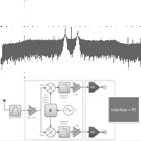
Signal processing plays a crucial role in radio telescope observations, defining the equipment used downstream and influencing project costs. Many radio telescopes are equipped with multiple parallel processing lines to handle more complex applications.
The Importance of Signal Processing
Why is it necessary to process the signal after it exits the receiver? The answer is straightforward: the data acquisition electronics are too slow to directly analyze signals in the gigahertz range. Data acquisition boards act as analog-to-digital converters connected to a computer or server via a PCI Express port, where the Fast Fourier Transform (FFT) is performed. Some radio telescopes utilize Field-Programmable Gate Arrays (FPGAs), which are integrated analog-to-digital converters on programmable electronic boards. These FPGAs perform the FFT to recover the spectrum before sending the data to the server. While there are cards capable of processing very high-frequency signals, their costs can be prohibitive. For instance, the AD9208BBPZ-3000 chip alone costs €1340. Therefore, it is more cost-effective to process the signal and analyze it at a lower frequency. Additionally, transmitting high-frequency signals through cables is challenging, and using amplifiers can degrade the signal.
To address these issues, the spectrum of the signal is transposed to a lower frequency.
How to Transpose a Signal's Spectrum to Another Frequency
The first step is to determine the target frequency for transposing the signal. Affordable data acquisition cards, often referred to as DAQ (Data Acquisition Cards), typically operate around 150 MHz. If one aims to observe a signal near 1240 MHz, the spectrum must be transposed to 70 MHz. This process requires a mixer:
A mixer from Mini Circuits.
The mixer takes the input signal to be transposed along with a reference signal. It is represented by a circle with a cross at its center. The reference signal is generated by a local oscillator, which will be explained later.
Mixing the signals produces two outputs: Sm = (Sa + Sr) and Sm = (Sa - Sr), where Sa is the antenna signal, Sr is the reference signal, and Sm is the mixed signal. This process generates one signal at a lower frequency and another at a higher frequency.
Data Acquisition Cards
PCI Express Cards:
These PCI Express acquisition cards are essentially ADCs on a high-speed bus. Since they are directly connected to a server, the resulting infrastructure is simplified. The server runs its acquisition program, which controls the cards, retrieves the signal, and performs the FFT using the graphics card.
FPGAs:
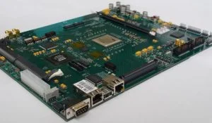
FPGAs are programmable boards equipped with processors. Models have been developed for large radio telescopes, such as the one in Nançay. They include an ADC and can perform calculations, including FFTs, thanks to their processors. Once the FFT is completed, they can send their results to a central server for data aggregation.
RTLSDR Keys:
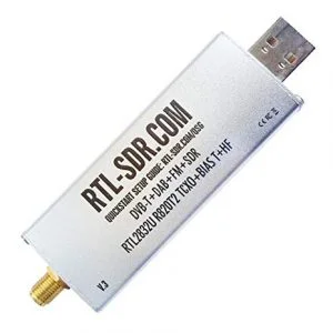
RTLSDR keys are user-friendly and compatible with various platforms (Linux, Windows, and even Android). Numerous online resources, programs, and libraries are available for their use. They are relatively inexpensive, costing only a few dozen euros, while some advanced models may reach around €200.
Filters
In radio astronomy, filters are essential. A processing line consists of multiple filters. At the output of the antenna, filtering is performed to isolate the desired frequency band. After the signal has been transposed, further filtering is necessary to eliminate the second signal generated by this operation.
A Complete Processing Line
Below is a diagram of a complete processing line:
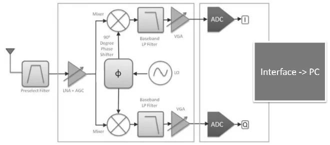
The triangles represent amplifiers, while the circle with a wave in the center denotes the local oscillator. The central square retrieves the reference signal and sends it to the mixers, but one of its outputs is phase-shifted by 90 degrees. This configuration allows two ADCs to acquire the signal simultaneously, and their data are concatenated to create a quadrature or IQ signal. The other squares represent filters that exclude unwanted frequencies to prevent interference. Next, we will move on to data processing.